Current Transformer Circuit Diagram
14+ current transformer circuit diagram Current transformer installation for three phase power supply- ct coil Current transformer circuit equivalent transformers electrical sizing wire selection engineering substations simplified guide portal wiring
Guide to selection of current transformers and wire sizing in substations
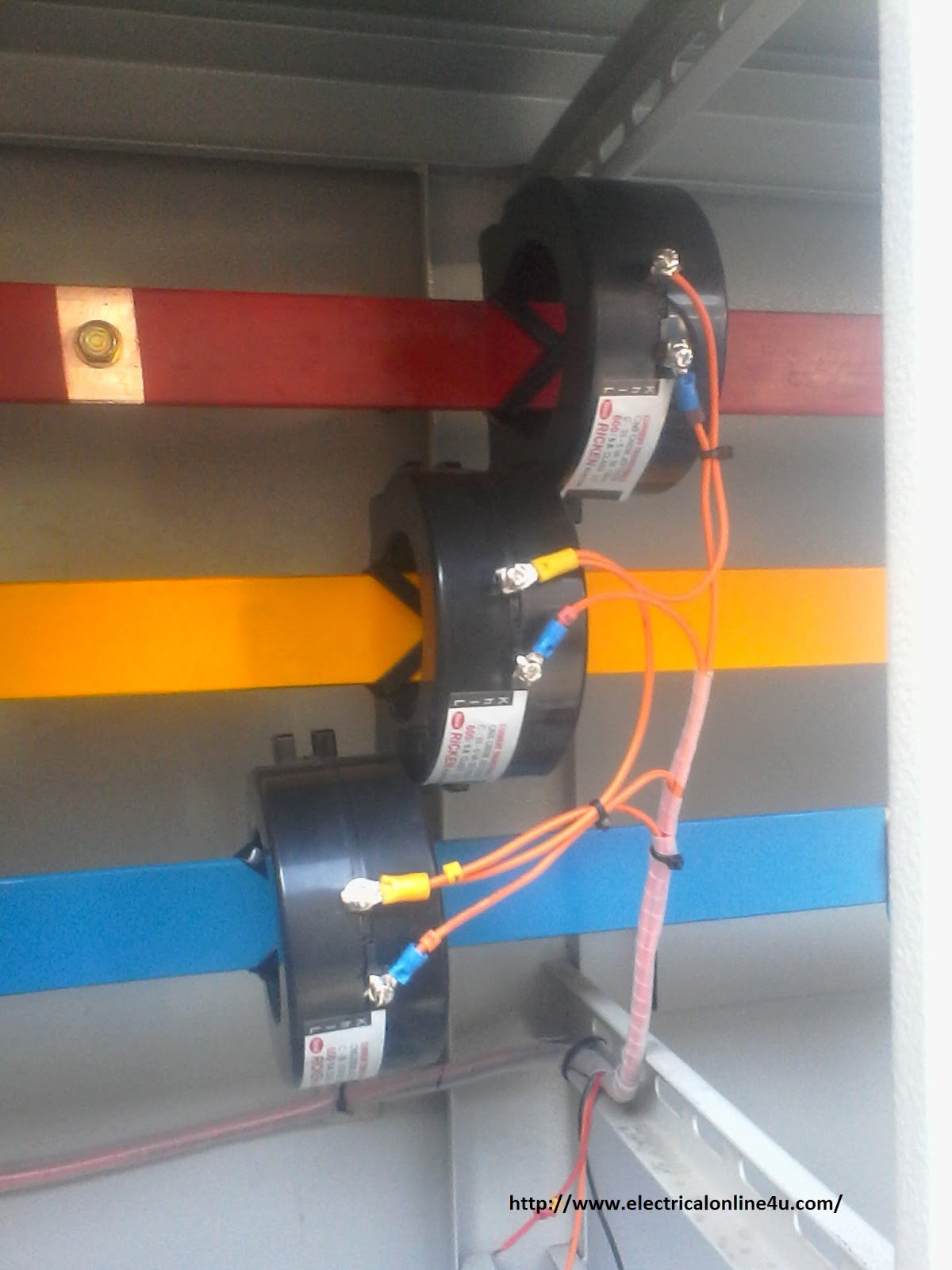
Transformer current diagram circuit potential loaded electrical transformers connected typical standard Transformer potential diagram circuit current difference between electrical transformers gif fig find android Current transformer installation for three phase power supply- ct coil
Current transformer wiring installation ct diagram phase coil three power supply electrical coils
Difference between current transformer and potential transformerElectrical topics: circuit diagram of loaded current transformer and Transformer spacoCurrent transformer wiring installation ct diagram phase coil three power meter connect electrical supply coils amp so.
Guide to selection of current transformers and wire sizing in substationsEquivalent circuit of transformer referred to primary and secondary What is current transformer (ct)? definition, construction, phasorEquivalent circuit of transformer referred to primary and secondary.

Current transformers voltage core low turns winding inside cross primary section required ag mbs measuring higher due number
Transformer secondary circuit equivalent primary side actual referred electrical voltage determination parameters fig gif winding electricalacademiaTransformer electricalbaba equivalent Transformer circuit equivalent phasor secondary primary side referred parameters form voltage electrical resistance fig ratio electricalacademiaWinding current transformers in low voltage.
Current transformer and potential transformer, circuit diagram, workingTransformer circuit electrical Current transformer and potential transformer, circuit diagram, working14+ current transformer circuit diagram.

Transformer current circuit ct diagram secondary types phasor construction primary definition circuitglobe
Transformer electricalworkbookWhat is current transformer (ct)? .
.


What is Current Transformer (CT)? - Working, Types, Applications

What is Current Transformer (CT)? Definition, Construction, Phasor

Equivalent Circuit of Transformer Referred to Primary and Secondary

Guide to selection of current transformers and wire sizing in substations

14+ Current Transformer Circuit Diagram | Robhosking Diagram

electrical topics: Circuit Diagram of Loaded Current Transformer and

14+ Current Transformer Circuit Diagram | Robhosking Diagram

Equivalent Circuit of Transformer Referred to Primary and Secondary

Difference between Current Transformer and Potential Transformer