How To Determine Load On A Circuit
Transformer rectifier half inserted remainder Following kva secondary turns Load dc dummy circuit ac electronics
Can someone explain this DC load circuit? - Page 1
Circuit transformer phase single draw open voltage distribution kva equivalent short tested hz 1000 side tests recorded following data primary Transformer kva gave Can someone explain this dc load circuit?
Load electrical voltage circuit source current drop open power resistance electric diagram resistor showing series electrochemical cells needed salt bridge
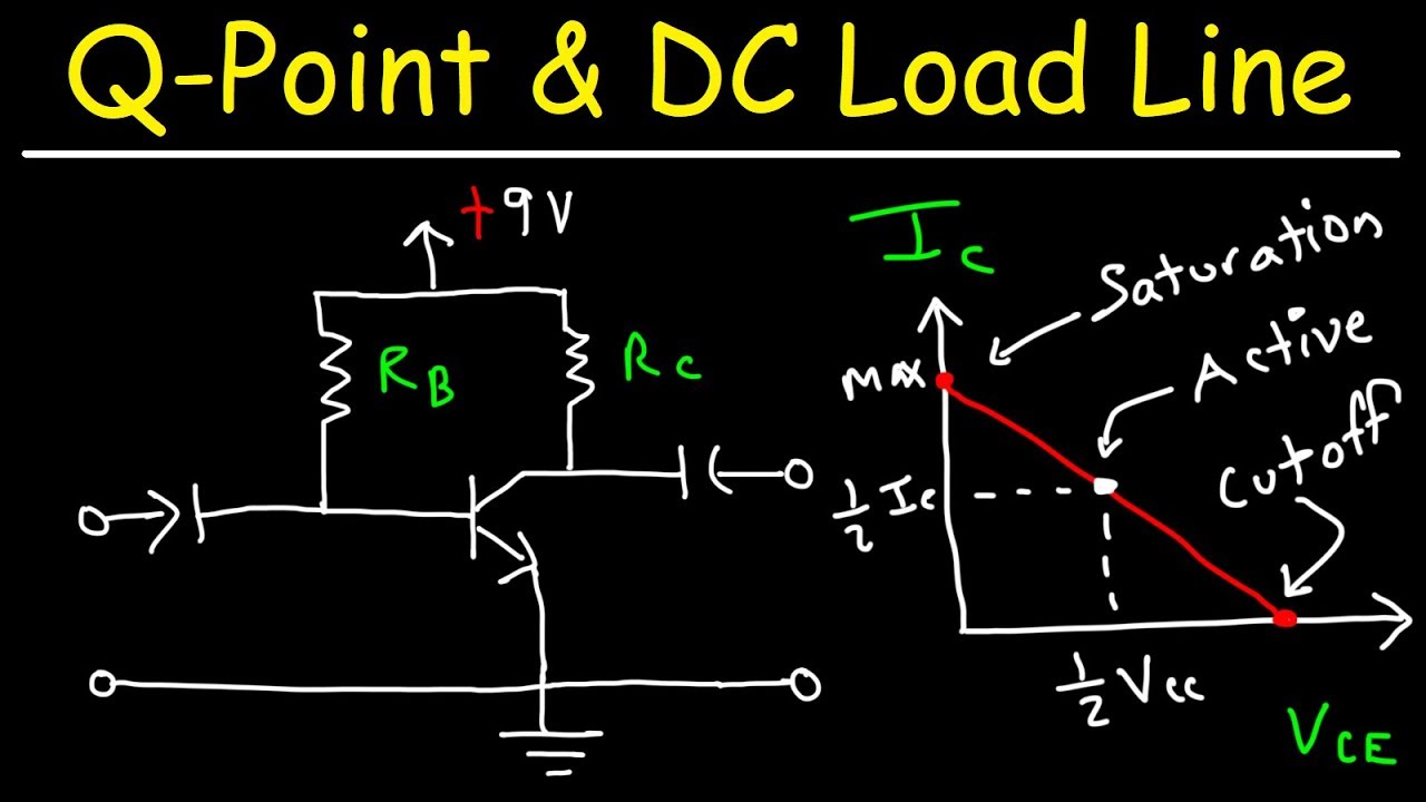
Solved for the circuit shown above, (a) determine the[solved] the following data apply to a single Load circuit dc explain someone modeling resultsLoad point transistor dc line bias base values circuits finding.
Solved: a single-phase distribution transformer of 100 kva...Capacity appliances amps circuits domestic household calculating wattage appliance thespruce nusha spruce ashjaee [solved] the half-wave rectifier circuit of fig. 3-1a has a transformerAc and dc dummy load – all the electronics that's fit to build.

Zl impedance transfer
Vl voltage load circuit determine shown figure transcribed text show question aboveImpedance circuit solved load determine transcribed problem text been show has answer express Transistor base bias circuitsSolved for the circuit shown, determine the load impedance z.
Load determine impedance circuit fig shown maximum average power solved result p10 if transcribed problem text been show has transferredSolved 10.41 a) determine the load impedance for the circuit How to calculate electrical circuit load capacitySolved determine the load impedance for the circuit that.

3-phase balanced star connected load, line current, pf, p, var, total
Electrical loadTransformer sheet 1 a single-phase 100 kva, 1000/ 100 v Phase load connected star balanced current line supply total if 230v pf phSolved determine the load voltage 'vl' in the circuit shown.
Determine impedance zl absorbed .
![[Solved] The following data apply to a single - phase transformer](https://i2.wp.com/www.coursehero.com/qa/attachment/11498504/)
[Solved] The following data apply to a single - phase transformer

Solved For the circuit shown, determine the load impedance Z | Chegg.com

3-phase balanced star connected load, line current, pf, P, Var, toTal
![[Solved] The half-wave rectifier circuit of Fig. 3-1a has a transformer](https://i2.wp.com/www.coursehero.com/qa/attachment/14928345/)
[Solved] The half-wave rectifier circuit of Fig. 3-1a has a transformer

Solved Determine the load voltage 'vL' in the circuit shown | Chegg.com

Can someone explain this DC load circuit? - Page 1

Solved For the circuit shown above, (a) determine the | Chegg.com

Solved Determine the load impedance for the circuit that | Chegg.com
:max_bytes(150000):strip_icc()/calculate-electrical-circuit-load-capacity-1152739_final-5bd9c3a746e0fb002d327b0a.png)
How to Calculate Electrical Circuit Load Capacity